- Nano-selective forward osmosis technology by SideStroem featured in Everything About Water - February 10, 2024
- SideStroem and Singapore Institute of Technology featured in AsianScientist - April 29, 2023
- SideStroem joins world class accelerator program - November 12, 2022
Forward osmosis can reduce scaling and increase top brine temperature in thermal desalination (Multi-stage flash distillation, MSF) processes

In their article “Viability of integrating forward osmosis (FO) as pretreatment for existing MSF desalting unit” Darwish et. al. investigate the viability of using forward osmosis to reduce feed water scale constituents in MSF plants thus allowing for an increase in top brine temperature (TBT) resulting in increased efficiency of the MSF plant.
Briefly, the study concludes that a retro-fitted Forward Osmosis system is technically viable, however, economical viability depends heavily on FO membrane cost.
In this regard, it is interesting to note that Modern Water recently (January 2016) signed a joint product development and commercialization agreement with Bilfinger Deutsche Babcock Middle East aiming to integrate forward osmosis based pre-treatment and MSF desalination plants (both existing and under development) to improve plant efficiency.
The MSF/FO integration described above is a great example of using a stand-alone forward osmosis system for industrial process optimization applications; ForwardOsmosisTech
So how does an MSF plant operate?
The Multi-stage flash distillation process in a widely used means of seawater desalination based on evaporation. Fundamentally, an MSF desalination plant works by heating saline water to produce vapor, which is then condensed to produce fresh water.
One of the biggest challenges in thermal desalination processes is scaling (precipitation of salts such as calcium sulfate as well as other sulfates and carbonates). Calcium sulfate, for example, precipitates above 115°C, which limits the top brine temperature and thus the efficiency of the distillation process. As a consequence, a substantial fraction of the OPEX costs in large-scale MSF plants is taken up by anti-scaling chemicals.
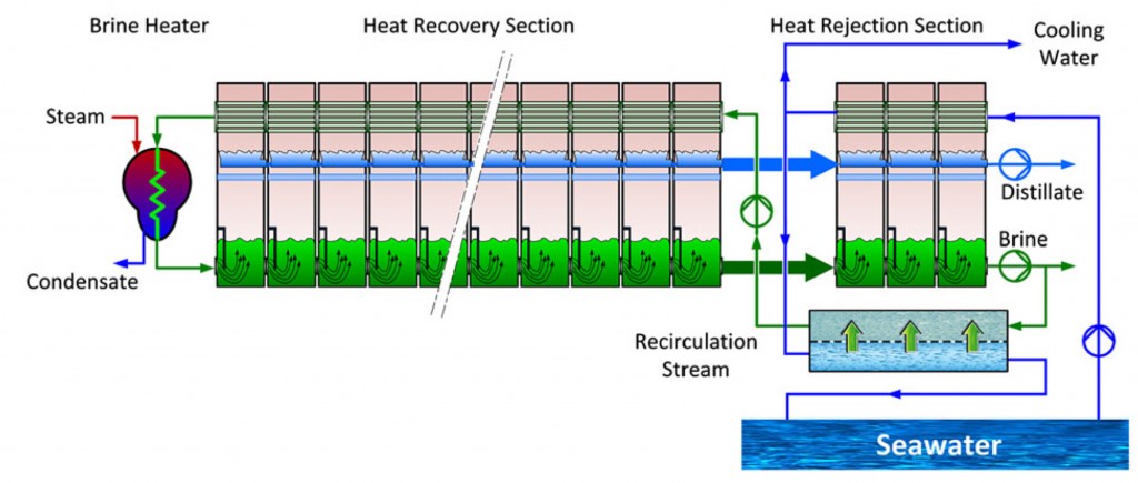
As illustrated below, the MSF process consists of a series of “stages” ranging in temperature (from hot to cold) and pressure (from low to lower). Circulating seawater provides the condenser coolant in individual stages and is heated as it passes through the system. At the heating section, additional heat is transferred to the seawater stream (typically raising the temperature up to 110°C) and it then enters into successive stages with lower temperature and pressure. Due to the gradually reduced (lower than atmospheric) pressure in each stage, the seawater immediately evaporates (flashes) upon entering stages.

Large MSF plants are divided into heat recovery and heat rejection sections for increased operational stability under conditions where the feed water temperature fluctuates. The division also has the added benefit of only having to treat (degassing and removal of scalants) the make-up seawater fraction entering the system.
Where does forward osmosis fit in?
As described in the work by Darwish et. al., a forward osmosis system is used to pretreat the make-up seawater entering the MSF process loop. Briefly, the feed seawater enters the forward osmosis system as the feed water while the recirculating brine acts as the draw solution. During the process, the recirculating brine is diluted with fresh water that does not contain scaling precursors. Darwish et. al. have demonstrated that the FO-mediated removal of scaling precursors in the make-up water allows for the top brine temperature to be increased from 110° C to 135° C thus significantly improving the efficiency of the MSF process.


This process lends its self more to existing plants rather than new build. The raising of the TBT allows an increase in GOR so less steam is required and the MSF process becomes more efficient or more distillate can be produced but with a higher steam consumption. Adding capacity to existing plants, depends what design margins were originally used, with older designs normally having much higher margins. It’s far more likely that the process would be used for energy consumption reductions, with significantly less stream used. This comes about because of how large scale power and water plants are designed normally for summer operation where electricity demand is much higher.
I and my co-authors wrote a detailed paper on this process a few years ago, where it was shown that for a typical power and water plant in the GCC that an annual fuel saving of about 8% was achievable. This is highly significant, given other technologies to reduce the fuel consumption for such plants are much lower. The payback period depends on the fuel cost, I reported a payback period of less than two years for a typical installation.